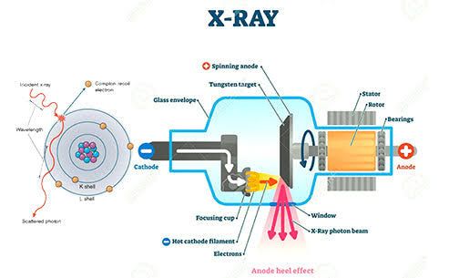
As a critical component in diagnostic imaging, the X-ray tube’s performance, longevity, and safety are paramount. Understanding its operational parameters, heat management, common failure modes, and systematic maintenance is essential for any professional involved in X-ray equipment.
Understanding X-ray Tube Rating and Its Applications
X-ray tube rating refers to the maximum electrical and thermal limits within which an X-ray tube can be safely operated without causing damage or significantly reducing its lifespan. Exceeding these limits can lead to immediate tube failure, compromised image quality, or long-term degradation.
1. Definition and Key Parameters
Tube rating is defined by several inter-related parameters that dictate the permissible X-ray exposure settings:
- Kilovoltage Peak (kVp): The maximum voltage applied across the X-ray tube during an exposure, directly influencing the penetrative power of the X-rays.
- Milliamperage (mA): The current flowing through the filament, determining the number of electrons (and thus X-ray photons) produced per second.
- Exposure Time (s): The duration for which X-rays are generated.
- Milliampere-seconds (mAs): The product of mA and time (mA x s), representing the total quantity of X-ray photons produced. This is a primary indicator of the total heat load on the anode.
- Focal Spot Size: The effective area on the anode target from which X-rays are emitted. Smaller focal spots offer better spatial resolution but concentrate heat on a smaller area, thus having lower heat capacity.
- Anode Rotation Speed: High-speed rotation (e.g., 10,000 rpm) allows for wider heat distribution on the anode track, increasing tube capacity compared to standard speed (e.g., 3,000 rpm).
2. Rating Charts and Curves
Manufacturers provide detailed rating charts and curves to guide safe operation:
- Single Exposure Rating Chart: Illustrates the maximum permissible kVp and mAs combinations for a single exposure, often categorized by focal spot size and anode speed. This chart is crucial to prevent instantaneous damage.
- Anode Thermal Characteristic (Heating/Cooling) Curve: Shows how quickly the anode heats up during successive exposures and how quickly it cools down. Anode heat units (HU) are typically used for this calculation.
- Housing Thermal Characteristic (Heating/Cooling) Curve: Indicates the heat capacity and cooling rate of the entire X-ray tube housing, which encompasses the anode, cathode, and the surrounding oil. This prevents damage to the housing and ensures long-term system stability.
3. Importance and Applications
- Prevention of Tube Damage: Adhering to ratings prevents common issues like anode cracking, pitting, bearing damage, or filament burning out.
- Ensuring Image Quality: Consistent tube performance, within its limits, ensures stable X-ray output and reliable image quality.
- Extending Tube Life: Operating within specified parameters significantly prolongs the operational life of an expensive X-ray tube.
- Patient and Operator Safety: Prevents equipment malfunction that could lead to radiation leaks or electrical hazards.
- Guiding Exposure Settings: Radiographers use these ratings to select appropriate exposure factors (kVp, mAs) for different anatomical regions and patient sizes, ensuring diagnostic quality while protecting the equipment.
Effective Cooling of the X-ray Tube
A fundamental challenge in X-ray tube operation is the immense heat generated. Only about 1% of the input electrical energy is converted into X-rays; the remaining 99% is dissipated as heat. Managing this heat is critical for tube longevity and performance.
1. Heat Generation and its Consequences
When high-speed electrons strike the anode target, their kinetic energy is largely converted into heat. Without efficient cooling, this intense heat can lead to:
- Anode Pitting and Cracking: Localized melting or stress fractures on the focal track, leading to reduced X-ray output, inconsistent beam, and arcing.
- Bearing Damage: Overheating of the anode bearings can cause lubrication breakdown, leading to increased friction, noise, and anode seize-up.
- Filament Evaporation: Excessive heat from the anode can contribute to accelerated evaporation of the cathode filament material, thinning it and eventually causing failure.
- Vacuum Deterioration: High temperatures can cause gasses to be released from the tube materials, leading to a poorer vacuum and increasing the risk of arcing.
- Reduced Tube Life: Cumulative thermal stress significantly shortens the operational lifespan of the tube.
2. Cooling Mechanisms
X-ray tubes employ multiple cooling mechanisms to dissipate this heat:
Anode Cooling
- Rotating Anode: The primary method. Instead of a stationary target, the anode rotates at high speed (typically 3,000-10,000 rpm), spreading the heat generated by the electron beam over a much larger area of the focal track.
- Anode Material Properties: The target typically consists of a Tungsten-Rhenium alloy embedded in a Molybdenum or Graphite disc. Tungsten has a high melting point and atomic number, while Molybdenum and Graphite are excellent heat conductors and provide a lightweight, high-capacity heat sink.
- Radiant Cooling: Heat radiates from the heated anode surface into the vacuum and is absorbed by the tube housing.
- Conduction into Anode Stem: Heat is conducted along the anode stem into the oil bath surrounding the tube insert.
Housing Cooling
The glass or metal envelope of the tube insert is encased within a protective, lead-lined metal housing filled with a dielectric oil. This oil serves multiple purposes:
- Electrical Insulation: Prevents arcing between the high-voltage components and the grounded housing.
- Heat Transfer: The oil effectively conducts heat away from the X-ray tube insert (anode, cathode, and envelope) to the outer housing.
- Oil Circulation:
- Convection: Natural circulation of heated oil within the housing.
- Forced Air Cooling: Fans blow air over the fins of the tube housing, which act as a heat exchanger, facilitating heat transfer from the oil to the ambient air.
- Water Cooling (for high-power tubes): For very high-capacity tubes (e.g., in CT scanners), a closed-loop water cooling system circulates water through a heat exchanger within the housing, offering superior heat dissipation. The water is then cooled by a radiator system.
3. Heat Units (HU)
To quantify the heat load on an X-ray tube, the concept of Heat Units (HU) is used.
- Single-phase generator: HU = kVp × mA × s
- Three-phase or High-Frequency generator: HU = 1.35 × kVp × mA × s (The factor 1.35 accounts for the more consistent voltage waveform, leading to more efficient X-ray production and thus more heat per mAs).
Understanding Heat Units is crucial for plotting exposures on anode and housing cooling curves to ensure the tube is operated within its thermal limits, allowing adequate time for cooling between exposures or series of exposures.
Common X-ray Tube Faults and Their Remedies
Despite robust design and cooling, X-ray tubes can develop faults over time due to wear, thermal stress, or other factors. Prompt identification and appropriate action are key to minimizing downtime and ensuring safety.
Common Faults and Symptoms
- Filament Failure (Open Filament/Burned-out Filament):
- Symptoms: No X-ray output, filament not glowing when observed through the tube port (if visible), “no X-ray” error message.
- Causes: Prolonged use (normal wear), excessive heating (e.g., high mA settings, prolonged pre-heating), voltage fluctuations, or repeated sudden high current surges.
- Remedy: Tube replacement is necessary as the filament is an integral part of the cathode assembly.
- Anode Bearing Failure:
- Symptoms: Unusual, loud spinning or grinding noise during anode rotation (audible immediately after exposure or during rotor preparation), erratic anode speed, streaky or blurred images (due to unstable focal spot).
- Causes: Overheating (leading to breakdown of the lubricant within the bearings), normal wear and tear over time, or manufacturing defect.
- Remedy: Tube replacement. Bearings are sealed within the vacuum envelope and cannot be serviced.
- Anode Pitting or Cracking:
- Symptoms: Reduced X-ray output efficiency, inconsistent image density, arcing within the tube, visible damage on the focal spot track (requires specialized tools to observe).
- Causes: Repeated high heat loads, exceeding single-exposure ratings, rapid successive exposures without adequate cooling, or a sudden, massive overload.
- Remedy: Tube replacement.
- Arcing (Tube Gassing/Vacuum Loss):
- Symptoms: Sudden flash or spark inside the tube during exposure, tripping of the high-voltage circuit breaker, error messages related to high voltage or tube protection, erratic X-ray output, strong ozone smell.
- Causes: Deterioration of vacuum quality (gassing from tube materials, micro-leaks), contamination inside the tube, arcing across cracked insulation, or excessive kVp.
- Remedy: Minor gassing might be temporarily resolved by a “tube conditioning” or “seasoning” procedure (gradual ramping up of kVp and mA). However, persistent arcing typically indicates a need for tube replacement.
- Oil Leaks or Low Oil Level in Housing:
- Symptoms: Visible oil drips around the tube housing, reduced cooling efficiency leading to housing overheating alarms, or error messages related to cooling system.
- Causes: Degradation of seals and gaskets over time, physical damage to the housing, or improper sealing during installation.
- Remedy: Identify and repair the leak source (e.g., replace gasket, mend housing), then refill the housing with proper dielectric oil and bleed any air.
- Collimator Malfunction:
- Symptoms: Incorrect X-ray field size (too large or too small), unevenly shaped field, illumination light not aligning with the X-ray field.
- Causes: Motor failure, control circuit issues, physical obstruction of collimator leaves, or misalignment.
- Remedy: Repair or replace the faulty collimator component, followed by calibration of the light and X-ray fields.
- High-Voltage Cable Issues:
- Symptoms: Arcing around cable connectors, intermittent X-ray output, safety interlock trips, burning smell.
- Causes: Physical damage to the cable insulation, loose connections, or moisture ingress.
- Remedy: Inspection of connections, repair of damaged insulation (if minor and safe), or complete cable replacement. This is a significant safety hazard and requires immediate professional attention.
- Generator Faults:
- Symptoms: No X-ray output, specific error codes on the control console (e.g., “HV error,” “inverter fault”), power fluctuations.
- Causes: Component failure within the high-voltage generator (e.g., rectifiers, capacitors, transformers, inverter boards), power supply issues.
- Remedy: Requires diagnosis and repair by a qualified service engineer, often involving replacement of specific electronic components or circuit boards.
General Troubleshooting Approach
- Observe and Document: Note all symptoms, error codes, and the conditions under which the fault occurred.
- Safety First: Always prioritize electrical and radiation safety. Disconnect power if necessary.
- Consult Manuals: Refer to the equipment’s service and operator manuals for specific troubleshooting steps and error code interpretations.
- Isolate the Problem: Determine if the fault is localized to the tube, generator, control console, or other peripheral components.
- Professional Intervention: Most X-ray tube and generator faults require the expertise of a certified biomedical engineer or service technician. Do not attempt complex repairs without proper training and tools.
Care and Maintenance of X-ray Equipment
Proactive care and systematic maintenance are crucial for ensuring the longevity, optimal performance, and safety of X-ray equipment. Adherence to manufacturer-recommended maintenance schedules is paramount.
Importance of Care and Maintenance
- Extends Equipment Lifespan: Regular maintenance prevents premature wear and tear, significantly prolonging the operational life of expensive components like the X-ray tube.
- Ensures Optimal Performance: Calibrated and well-maintained equipment consistently produces high-quality diagnostic images.
- Enhances Safety: Addresses potential electrical hazards, radiation leaks, and mechanical failures before they become critical.
- Ensures Regulatory Compliance: Many regulatory bodies require documented routine maintenance and calibration for X-ray equipment.
- Reduces Downtime and Costs: Prevents costly, unscheduled repairs and minimizes disruptions to clinical operations.
Routine Checks (Daily/Weekly – Operator Level)
- Visual Inspection:
- Check all cables and connectors for signs of wear, fraying, or damage.
- Inspect the tube housing for oil leaks or physical damage.
- Verify all indicator lights and alarms are functioning correctly.
- Ensure all mechanical movements (e.g., tube stand, table) are smooth and locks are secure.
- Cleanliness:
- Wipe down the X-ray tube housing, control console, and patient contact surfaces with appropriate disinfectants. Avoid harsh chemicals that could damage surfaces.
- Keep the area around the equipment free of dust and debris.
- Collimator Light and Field Accuracy:
- Periodically check that the collimator light field accurately corresponds to the X-ray field. A dedicated test tool may be used.
- Ensure the light is bright enough.
- Emergency Stop Buttons:
- Briefly test the functionality of all emergency stop buttons to ensure they immediately cut power to the system.
Scheduled Preventive Maintenance (Monthly/Quarterly/Annually – by Qualified Personnel)
This level of maintenance requires specialized tools, knowledge, and often involves system calibration.
X-ray Tube Specific Checks:
- Anode Rotation Check: Verify the anode rotation speed and listen for unusual noises.
- Cooling System Inspection: Check oil levels in the housing, inspect heat exchangers (radiator fins) for obstructions, verify fan operation (for air-cooled systems) or water flow and purity (for water-cooled systems).
- Tube Conditioning/Seasoning: Perform tube conditioning (gradual increase of kVp/mA) if recommended by the manufacturer, especially after periods of inactivity, to maintain vacuum integrity and prevent arcing.
- Radiation Leakage Survey: Periodically check the tube housing for any radiation leakage, although this is often part of overall system quality assurance.
Generator and System-Wide Checks:
- High Voltage (kVp) Calibration: Verify the accuracy of the applied kVp against the selected value using a kVp meter.
- mA and Time Accuracy: Calibrate the mA output and exposure timer accuracy using a calibrated dosimeter or appropriate test device.
- Exposure Reproducibility: Ensure consistent X-ray output for identical exposure settings.
- Safety Interlocks: Test all safety interlocks (e.g., door interlocks, bucky interlocks, overload protection circuits).
- Grounding and Electrical Safety: Check all electrical connections for tightness and verify proper grounding. Perform electrical safety tests (e.g., leakage current).
- Mechanical Integrity: Lubricate moving parts, tighten loose fasteners, and inspect for wear in mechanical systems (e.g., tube supports, detents).
- Image Quality Assurance: Conduct regular phantom imaging to assess image quality parameters such as spatial resolution, contrast resolution, and noise.
- Software Updates: Ensure the system’s software is up-to-date according to manufacturer recommendations.
Operating Best Practices
- Warm-up Procedures: Always follow the manufacturer’s recommended warm-up procedure, especially at the start of the day or after the tube has been idle for an extended period. This gradually heats the anode, dissipates residual gas, and stabilizes the tube’s components, preventing thermal shock and arcing.
- Respect Tube Ratings: Never exceed the specified kVp, mA, or mAs limits for single or multiple exposures. Consult the tube rating charts diligently.
- Manage Heat Load: Allow adequate cooling time between exposures, particularly for high mAs techniques. Avoid rapid succession of high-output exposures unless the cooling system is designed for it (e.g., CT).
- Gentle Handling: For mobile or portable units, handle the equipment carefully to avoid shocks or vibrations that can damage internal components.
- Environmental Control: Operate the equipment within the specified temperature and humidity ranges. Ensure adequate ventilation to prevent overheating, and keep the environment clean to minimize dust ingress.
- Staff Training: Ensure all operators are thoroughly trained on the safe and correct operation of the equipment, including error recognition and initial troubleshooting steps.
Documentation
Maintain detailed records of all maintenance activities, including dates, issues found, remedies applied, parts replaced, and responsible personnel. This documentation is vital for tracking equipment history, ensuring compliance, and informing future maintenance decisions.

